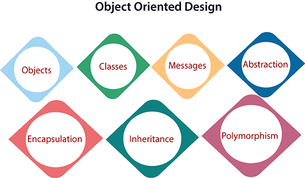
Object Oriented Design
May 12, 2020
After defining requirements and writing some use cases or user stories we start to transition from analysis, understanding the problem we’re trying to solve, to design, how we’re going to organize our solution.
Identifying the objects
To identify objects, we’ll go through all of our use cases and user stories and any other written requirements to pick out all of the nouns. – That’s one benefit of actually writing out all those descriptions.
Identifying class relationships
Once we have the potential objects picked out for our conceptional model, it’s useful to indicate the main relationships or associations between those concepts by drawing lines between the boxes.
Many of these relationships will be obvious but we can always reference our written use cases and user stories if needed.
Now it may seem like there are a lot of interesting details missing from here, and there’s no way we could start writing code based on this diagram but that’s okay. This is just a conceptional model to use for communication and to prompt ideas. The benefit of detailing these relationships is that it makes it easier to realize which objects interact with each other, meaning which objects have behaviors that affect other objects.
Identifying class responsibilities
We need to figure out the responsibilities for our conceptual objects to really identify what are, and what are not classes that we’ll need to create, and just as we started by picking out nouns in our written description to create a list of potential objects we can go back to the use cases and user stories to look for verbs, and verb phrases to identify responsibilities.
Now not all of these will necessarily become behaviors, some might need to be combined, some might need to be split apart, and some may not be needed at all or will be replaced by something else. But they’re a good starting point and will often prompt other discussions. – Something that isn’t always obvious, is where these responsibilities belong. Particularly if they affect different objects. Since our use case here has an active perspective, it’s oriented around what initiates a behavior not necessarily whose responsibility it is to perform that behavior. When asking the question of where should a behavior live, or whose responsibility is it? Remember that an object should be responsible for itself.
If your own design contains a central system or master object, that’s filled with lots of unrelated behaviors, and just seems to exist to control everything else around it? That’s a clue that you’re still thinking like a procedural programmer. Responsibilities should be distributed between your objects not stored in one master object an object should be responsible for itself, as much as possible. That’ll make maintaining and updating the application much easier in the future.
CRC Cards
One technique that can be useful during this stage of Object Oriented Design are CRC cards. Which stands for: Class, Responsibility, Collaboration. CRC cards contain the same information as the Conceptual Object Diagram, just in a different format. They’re drawn on index cards, and they’re meant to be simple. Easy to create, hand around, discuss, spread out on a conference table, and you dispose of it if you make a mistake, or change your mind. Each CRC cards represents one class, and it has three sections. The first C is the name of the class at the top, which is usually underlined. The R is the Responsibilities of the class, the things that it needs to take care of. And the second C is for the Collaborators, the other classes it interacts with. CRC cards typically use this format with the responsibilities taking up the left two-thirds of the card, and the collaborators on what’s remaining to the right.
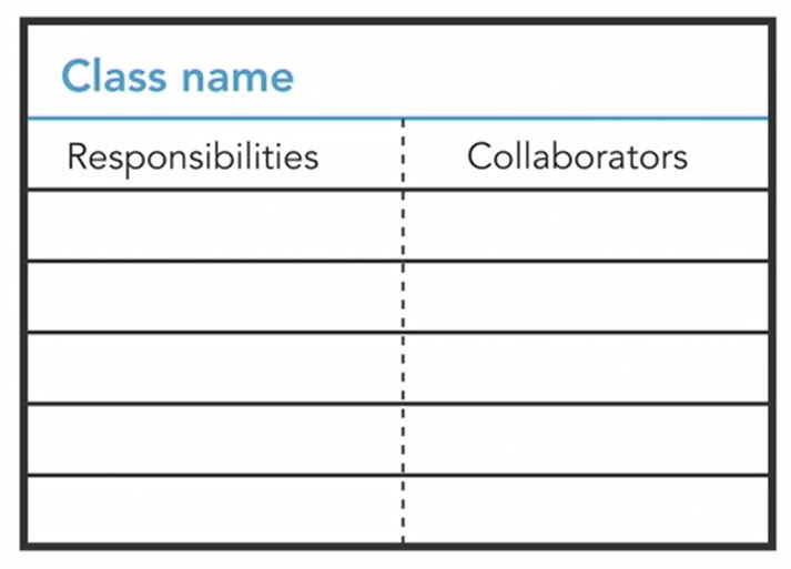
You may also hear these referred to as CRH cards for: Component, Responsibilities, and Helper. Those are effectively the same thing, just using different terms.
Whether you choose to use CRC cards, or a Conceptual Diagram, or some other method of your own. You should finish this phase of the object oriented design process, with at least the names and core responsibilities for the first set of classes you intend to code.
Class Diagram
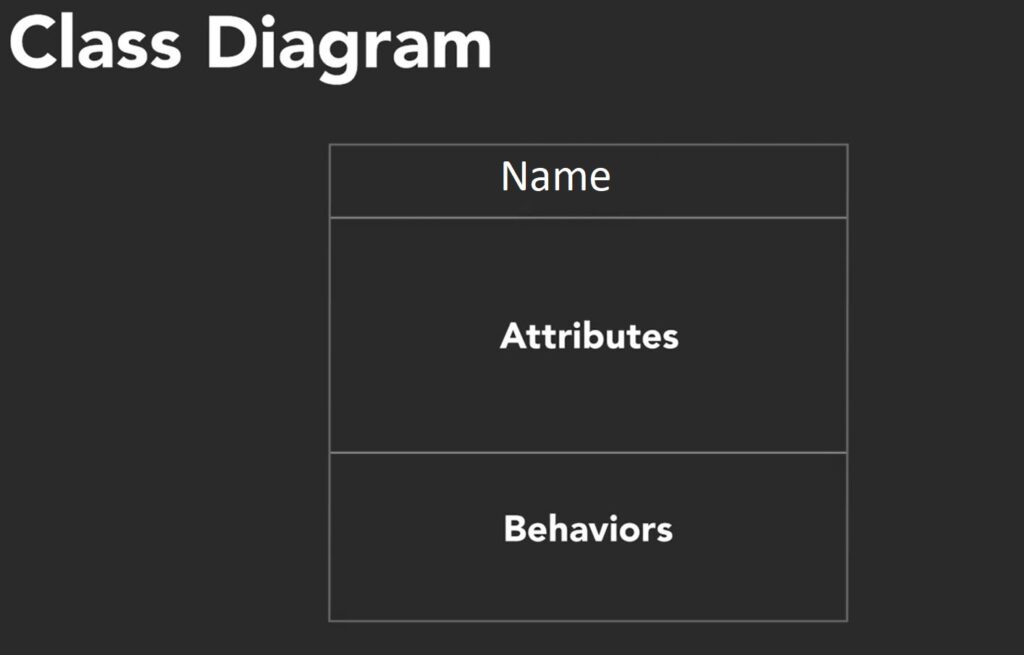
All works like writing requirements and use cases and building a conceptual model, was to figure out our first set of classes, so now it’s time to create a proper class diagram to visually represent them. And this is where specific object-oriented principles, like inheritance and polymorphism, can start coming into play. The most common format to use is the UML class diagram.
Each class should have a name written in the singular form, not plural, and the standard is to use an uppercase first letter, Now, you won’t know all of the attributes yet, because the focus so far has been on class responsibilities and behaviors, but start by writing down any obvious ones, and you can always add more later. Use whatever naming convention is typical for your programming language. I’m using the common camel case format here, which starts with a lowercase first letter and then uses uppercase for additional words. While it’s common to just write the attribute names, you can also suggest a data type using a colon.
I can also describe a default value, using an equal sign after the data type. Not all attributes need that, just where it’s relevant and important. As you’re initially creating class diagrams, don’t get hung up on knowing the exact data types to use.
When it comes to adding behaviors to our class diagram, we should have a good idea of what to write here from creating our conceptional object model and CRC cards. I’ll use the same camel case format as the attribute names. But since these represent operations, they’re usually named as short verb phrases; getShieldStrength, reduceShield, and simply move. It’s common practice to name methods that modify and retrieve attributes as get and set operations rather than things like change or retrieve. And some languages will even automatically generate getter and setter methods for you. Since these will eventually turn into code, we’ll add parenthesis containing any parameters. For example, the reduceShield method takes an integer as it’s input parameter. On the other side, I could also add a return type by putting a colon after the parenthesis followed by the return type I’m expecting back from the operation.
Now these classes may have a lot of functionality internally, but the focus here is on public visibility. What are the operations that other objects need to know about? And this is in line with the principle of encapsulation. To hide as much of the implementation as possible, and only share what’s absolutely necessary to expose to other classes. You’ll commonly see plus and minus signs before the attributes and methods in UML class diagrams. Which is referred to as controlling visibility. Minus indicates that a member should be private to the class, meaning it’s not directly accessible by other objects, and plus means the member should be public.
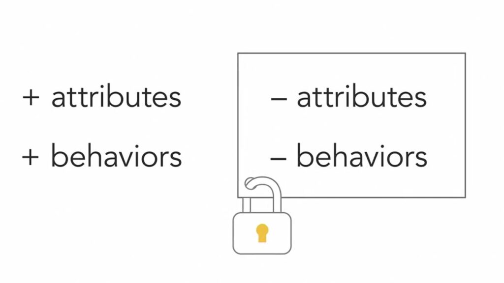
The rule here is to leave as many attributes and methods private as possible, and only make something public if you know another object will need to use it.
If you find yourself defining classes that are strangely devoid of any behavior, you might want to revisit those responsibilities. Do a little work with the requirements, written descriptions, and the conceptional model, or CRC cards. Your focus should really be on what object do rather than just viewing them as data structures.